Door Controller/Construction details
From ESCTL
Construction details
- Serial version: TX-TX, RX-RX from RS232 driver to Arduino
- Ethernet version: TX-RX, RX-TX from Ethernet driver to Arduino
- Suggested wiring order (refer to Door_Controller/Pinouts#Arduino_Pinout)
- 1 F-F 5V PSU -> Ethernet (Vdd)
- 5 M-F vIn/GND/Reader(D0,D1)/Voltage_Sense -> Arduino
- 3 M-F Arduino TX/RX, GND-> Ethernet
- TX(Ethernet)-> RX(Arduino)
- RX(Ethernet)-> TX(Arduino)
- 1 M-F Arduino CFG -> Ethernet
- 4 F-F Relay -> Arduino
Connection board
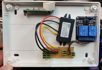
Currently constructed from RS 433-832 stripboard, cut to 15x5 sections (was 12x5 before moving lock connector to board)
- Brown/Blue cable length: cut to 75mm
- Voltage sense resistors: 4k7 connected to GND, 15k connected to Vin. Common joined and connected to Arduino A3
- Reverse voltage / flyback protection diode: 1N4004, with stripe connected to V+(lock) and other end connected to GND
Bi-colour LED
- Black/Red/Green cable length: cut to 30cm
- For LED SC07647
- Resistor value 120R
- Pin by flat edge: Red
- Centre pin: Ground
- Pin opposite flat edge: Green

