Door Controller/Construction details
From ESCTL
< Door Controller(Difference between revisions)
(→Connection board) |
(→Ethernet configuration) |
||
| (10 intermediate revisions by one user not shown) | |||
| Line 1: | Line 1: | ||
| + | [[File:20201130 202647.jpg|350px]] | ||
| + | |||
== Construction details == | == Construction details == | ||
* Serial version: TX-TX, RX-RX from RS232 driver to Arduino | * Serial version: TX-TX, RX-RX from RS232 driver to Arduino | ||
* Ethernet version: TX-RX, RX-TX from Ethernet driver to Arduino | * Ethernet version: TX-RX, RX-TX from Ethernet driver to Arduino | ||
| − | * Suggested wiring order | + | * Suggested wiring order (refer to [[Door_Controller/Pinouts#Arduino_Pinout]]) |
** 1 F-F 5V PSU -> Ethernet (Vdd) | ** 1 F-F 5V PSU -> Ethernet (Vdd) | ||
| − | ** 5 M-F vIn/GND/Reader/Voltage_Sense -> Arduino | + | ** 5 M-F vIn/GND/Reader(D0,D1)/Voltage_Sense -> Arduino |
** 3 M-F Arduino TX/RX, GND-> Ethernet | ** 3 M-F Arduino TX/RX, GND-> Ethernet | ||
| + | *** TX(Ethernet)-> RX(Arduino) | ||
| + | *** RX(Ethernet)-> TX(Arduino) | ||
** ''1 M-F Arduino CFG -> Ethernet'' | ** ''1 M-F Arduino CFG -> Ethernet'' | ||
** 4 F-F Relay -> Arduino | ** 4 F-F Relay -> Arduino | ||
== Connection board == | == Connection board == | ||
| + | [[File:20201130 202628.jpg|thumb]] | ||
| + | |||
Currently constructed from RS 433-832 stripboard, cut to 15x5 sections (was 12x5 before moving lock connector to board) | Currently constructed from RS 433-832 stripboard, cut to 15x5 sections (was 12x5 before moving lock connector to board) | ||
* Brown/Blue cable length: cut to 75mm | * Brown/Blue cable length: cut to 75mm | ||
* Voltage sense resistors: 4k7 connected to GND, 15k connected to Vin. Common joined and connected to Arduino A3 | * Voltage sense resistors: 4k7 connected to GND, 15k connected to Vin. Common joined and connected to Arduino A3 | ||
* Reverse voltage / flyback protection diode: 1N4004, with stripe connected to V+(lock) and other end connected to GND | * Reverse voltage / flyback protection diode: 1N4004, with stripe connected to V+(lock) and other end connected to GND | ||
| − | |||
| − | |||
== Bi-colour LED == | == Bi-colour LED == | ||
| Line 24: | Line 28: | ||
** Centre pin: Ground | ** Centre pin: Ground | ||
** Pin opposite flat edge: Green | ** Pin opposite flat edge: Green | ||
| + | |||
| + | == Ethernet configuration == | ||
| + | [[File:Example-esctl-ip-settings.jpg]] | ||
| + | |||
| + | Don't forget to also connect to the board and set the MAC address stored in EEPROM to match the address of the network card, as well as the serial number: | ||
| + | |||
| + | '''set mac 00-FA-0F-AB-12-34''' | ||
| + | |||
| + | '''set serial 123''' | ||
| + | |||
| + | == Front cover == | ||
| + | * 2mm hole for LED using drilling template (Approx 18mm in from each edge) | ||
| + | * File down head of LED for maximum diffusion | ||
| + | |||
| + | [[File:Esctl_node_led_diffuse.jpg|thumb]] | ||
| + | [[File:Esctl_node_front_rearview.jpg|thumb]] | ||
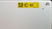
| + | [[File:Esctl_node_front_label.jpg|thumb]] | ||
Latest revision as of 15:22, 12 December 2020
Contents |
[edit] Construction details
- Serial version: TX-TX, RX-RX from RS232 driver to Arduino
- Ethernet version: TX-RX, RX-TX from Ethernet driver to Arduino
- Suggested wiring order (refer to Door_Controller/Pinouts#Arduino_Pinout)
- 1 F-F 5V PSU -> Ethernet (Vdd)
- 5 M-F vIn/GND/Reader(D0,D1)/Voltage_Sense -> Arduino
- 3 M-F Arduino TX/RX, GND-> Ethernet
- TX(Ethernet)-> RX(Arduino)
- RX(Ethernet)-> TX(Arduino)
- 1 M-F Arduino CFG -> Ethernet
- 4 F-F Relay -> Arduino
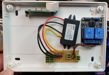
[edit] Connection board
Currently constructed from RS 433-832 stripboard, cut to 15x5 sections (was 12x5 before moving lock connector to board)
- Brown/Blue cable length: cut to 75mm
- Voltage sense resistors: 4k7 connected to GND, 15k connected to Vin. Common joined and connected to Arduino A3
- Reverse voltage / flyback protection diode: 1N4004, with stripe connected to V+(lock) and other end connected to GND
[edit] Bi-colour LED
- Black/Red/Green cable length: cut to 30cm
- For LED SC07647
- Resistor value 120R
- Pin by flat edge: Red
- Centre pin: Ground
- Pin opposite flat edge: Green
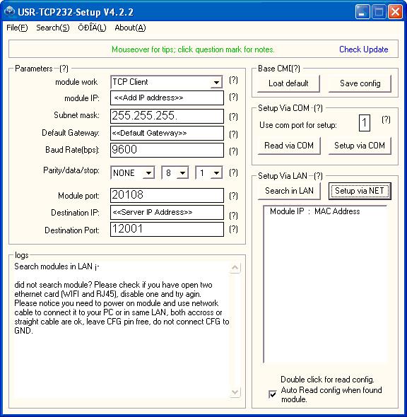
[edit] Ethernet configuration
Don't forget to also connect to the board and set the MAC address stored in EEPROM to match the address of the network card, as well as the serial number:
set mac 00-FA-0F-AB-12-34
set serial 123
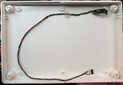
[edit] Front cover
- 2mm hole for LED using drilling template (Approx 18mm in from each edge)
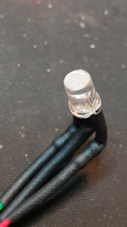
- File down head of LED for maximum diffusion
